
In modern electronics contract manufacturing and custom Box build assembly, precision begins long before a single wire is stripped or a terminal is crimped. At the heart of every reliable electrical system lies a clear, standardized document: the wire harness schematics.
Whether you are designing advanced medical devices, industrial automation systems, or automotive electronics, understanding how to read, create, and refine wire harness schematics is the single most critical step in taking a concept from design to flawless physical production.
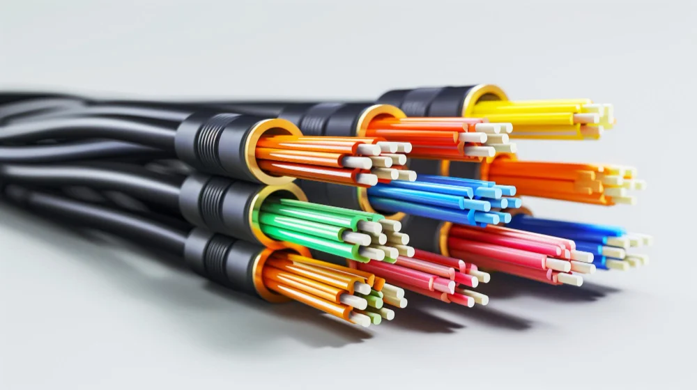
A wire harness schematic is a technical blueprint that maps out the electrical connections, components, pinouts, and routing logic of a custom wiring assembly. Unlike standard block diagrams that offer high-level overviews, schematics provide granular, actionable details required by manufacturing engineers, assembly technicians, and quality assurance teams.
While an electrical schematic details the logical flow of electrical signals across circuits, a manufacturing wire harness schematic goes further by incorporating specific physical parameters, such as:
To ensure smooth manufacturing without costly delay loops or back-and-forth inquiries, every professional wire harness drawing relies on standardized Electrical symbols and complete documentation parameters across several key areas:
Transforming a 2D engineering drawing into a fully functional 3D wire harness requires a structured sequence of prototyping and Manufacturing steps.
1.Schematic Review and Design for Manufacturability (DFM):
Validating the electrical layout prior to tooling.
Before cutting any wire, manufacturing engineers perform a comprehensive DFM audit on the wire harness schematics. This process checks for obsolete components, verifies terminal compatibility with wire gauges, ensures proper bend radii, and confirms that IPC-WHMA-A-620 compliance standards are met.
2.Formboard and Form-to-Scale Layout Creation:
Translating schematics into 1:1 physical assembly templates.
The 2D schematic details are translated into a 1:1 physical manufacturing template, known as a pegboard or formboard. This board outlines exact wire lengths, breakout branch points, connector locations, and tie-wrap positions to ensure exact repeatability during manual assembly.
3.Automated Wire Processing:
Precision cutting, stripping, and crimping.
Automated CNC wire processing machines measure, cut, and strip wires according to the length chart specified in the schematic BOM. Terminal applicators crimp connectors onto wire ends with calibrated force, frequently verified via cross-section crimp height testing.
4.Harness Routing and Integration:
Building the Harness branches and adding protective sleeving.
Assembly technicians lay out individual wires onto the formboard, following color-coded schematic pathways. Wires are bundled, laced, or sleeved using split loom, braided sleeving, or heat-shrink tubing to protect against abrasion, chemicals, and mechanical strain.
5.Automated Electrical Testing:
Continuity, short-circuit, and high-voltage validation.
Every completed harness is connected to an automated harness tester. The tester verifies pin-to-pin continuity against the schematic’s netlist, ensuring zero miswires, open circuits, or short circuits. High-pot (high-potential) testing may also be performed to verify insulation integrity.
Errors in schematic drawings can cause manufacturing bottlenecks, component scrap, and field failures. Addressing these common design missteps early ensures smooth execution:
One of the most frequent issues occurs when schematics detail connectors and Wires but omit secondary components like wire seals, strain relief boots, or specific heat-shrink tubing. Always ensure every sub-assembly part is listed with a manufacturer part number.
Designing tight 90-degree bends right at the Connector housing without accounting for strain relief causes terminal pull-out and conductor fatigue. Schematics and harness drawings must allow adequate clearance for wire entry and flexing.
Drawing connectors without clarifying whether the view shows the front (mating) face or the rear (wire insertion) view leads to mirrored pinouts—a costly mistake that renders harnesses completely unusable.
1.What is a wire harness schematic?
A technical blueprint mapping circuit connections, pinouts, wire gauges, and routing logic for custom wiring assemblies.
2.How does a schematic differ from a wiring diagram?
Schematics show circuit logic and signal pathways using electrical symbols; wiring diagrams focus on physical component placement inside a chassis.
Common tools include SolidWorks Electrical, EPLAN HarnessproD, AutoCAD Electrical, and Altium Designer.
The global quality standard for cable and wire harness assembly, defining acceptance criteria for soldering, crimping, and routing.
Mastering wire harness schematics is essential for bringing electrical and electromechanical products to life efficiently. A well-designed schematic eliminates ambiguity, shortens production lead times, prevents assembly errors, and serves as the foundation for rigorous quality control. Partnering with an experienced electronics contract manufacturer during the schematic phase ensures your designs are fully optimized for manufacturability, cost efficiency, and long-term reliability.